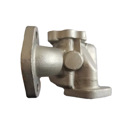
The structural characteristics of casting are mainly reflected in the specific process structures designed to meet the requirements of the casting process. These structures not only help improve the quality of castings but also simplify the manufacturing process and reduce costs. The following are common structural characteristics of cast parts:
1. Casting Fillets
To prevent cracks or shrinkage cavities at sharp corners due to stress concentration during cooling, the junctions of adjacent surfaces should be designed with fillets. Casting fillets also prevent molten metal from destroying the corners of the sand mold during pouring and reduce the risk of damage to the sand mold during demolding. The fillet radius is generally 0.2 to 0.4 times the wall thickness, with a common range of R3 to R5 mm. On drawings, it can be uniformly marked "Unspecified fillet R3 to R5".
2. Draft Angle
To facilitate the smooth removal of the wooden or metal mold from the sand mold, the inner and outer walls of the casting need to be designed with a certain draft angle along the demolding direction, called the draft angle. The draft angle is typically 1:100 to 1:20, approximately 1° to 3° for manual molding and reduced to 0.5° to 1° for machine molding. If the draft angle is small, it may not be shown in the drawing, but should be noted in the technical requirements.
3. Uniform and Reasonable Wall Thickness
The wall thickness of the casting should be as uniform as possible, avoiding areas that are too thick or too thin to prevent defects such as shrinkage cavities, cracks, or deformation due to inconsistent cooling rates. When different wall thicknesses must be connected, a smooth transition should be achieved through a transition slope to reduce stress concentration. Simultaneously, the wall thickness should not be less than the minimum allowable wall thickness of the material; otherwise, incomplete filling or cold shuts may occur.
4. Transition Line
Due to the presence of casting fillets, the actual intersection line on the casting surface becomes less obvious, but the theoretical intersection line still needs to be drawn on the part drawing; this is called the transition line. The transition line is drawn with a thin solid line, and its ends do not intersect with the fillets, leaving gaps to distinguish it from the actual intersection line.
5. Reinforcing Ribs and Bosses
To enhance the strength and rigidity of castings, thin-plate reinforcing ribs are often incorporated. Additionally, to ensure good contact during assembly, reduce machining area, and prevent drilling deviation, bosses, recesses, or countersinks are frequently designed.
6. Parting Surface and Simplified Structure
The casting shape should be simplified as much as possible, reducing the number of parting surfaces and avoiding lateral recesses to lower mold complexity and production costs. Complex internal cavities can be formed using sand cores, while the external shape should facilitate demolding.